Behind the Scenes of the Final Frontier: Our Tour with NASA’s “Launch Director” – 6

Step behind the scenes of space exploration with this dive into the awe-inspiring details of the Space Shuttle Atlantis, its thermal-protected wings to the onboard engines.

Imagine, if you will, stepping onto the grounds of NASA, where the air buzzes with the legacy of space exploration and the spirit of human achievement. It’s a place where dreams of the cosmos turn into reality. Our 2017 Launch Director tour not only brought us face-to-face with the marvels of space travel but allowed me to delve into the intricate details of one of NASA’s most iconic spacecraft: the Space Shuttle Atlantis. In this episode 6 of our adventure, we continue exploring the engineering marvel that is Atlantis, focusing on its wings, rear stabilizer, and onboard engines—elements critical to its legendary missions.

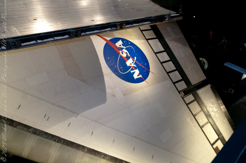
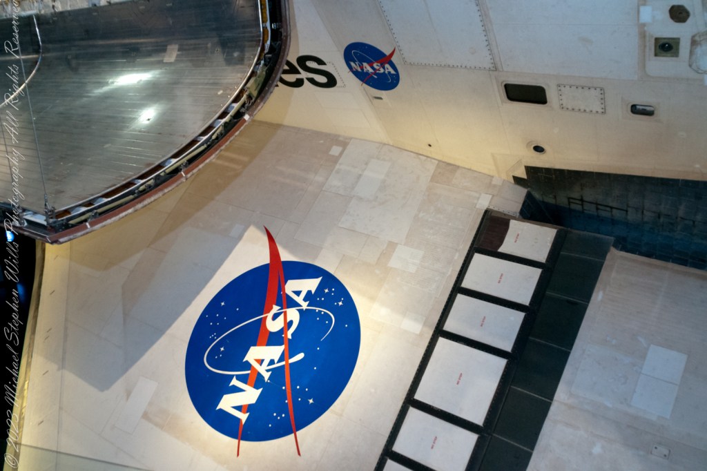
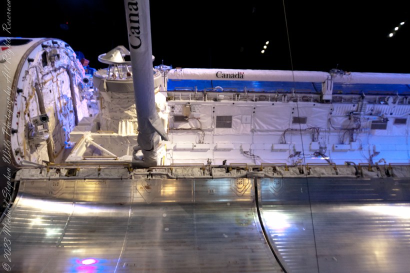
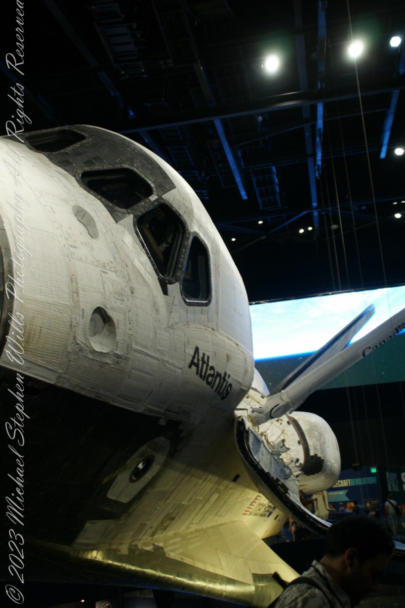
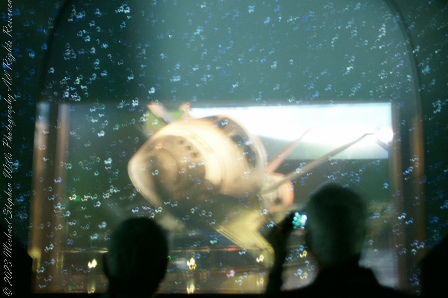
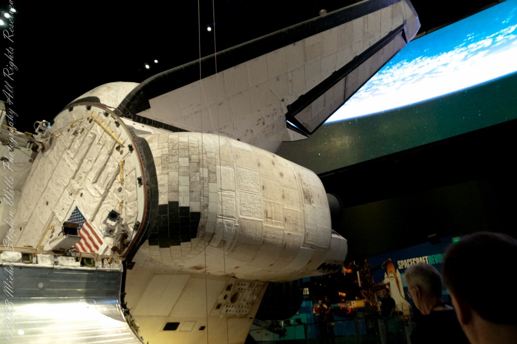
The Space Shuttle Atlantis, a name synonymous with discovery and exploration, represents a pinnacle of human ingenuity. As you walk around the Atlantis exhibit, you can’t help but be awed by the shuttle’s design, particularly its wings. The wings of Atlantis, with a wingspan of about 78 feet, are not just structures of metal and composite materials; they are the shuttle’s lifeline during re-entry into Earth’s atmosphere. These delta-shaped wings are designed to withstand the scorching temperatures of re-entry, allowing Atlantis to glide back to Earth with grace and precision. The material covering the wings, known as the Thermal Protection System (TPS), consists of thousands of heat-resistant tiles and reinforced carbon-carbon panels, safeguarding the shuttle and its crew from temperatures exceeding 1,650 degrees Celsius.

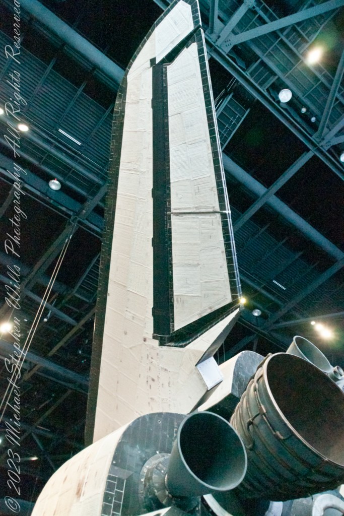
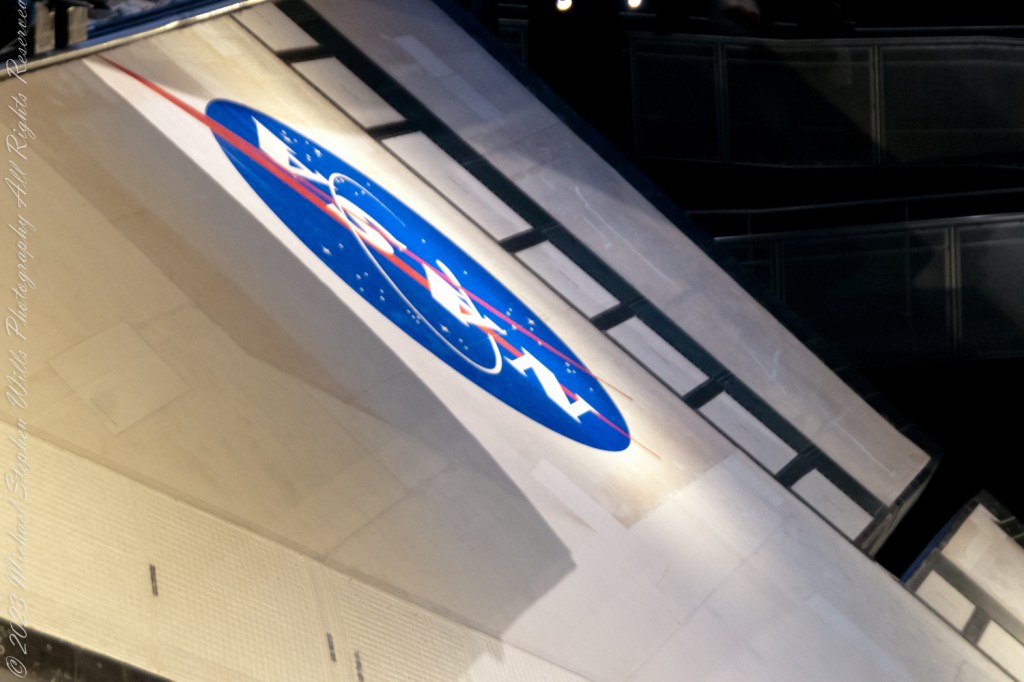
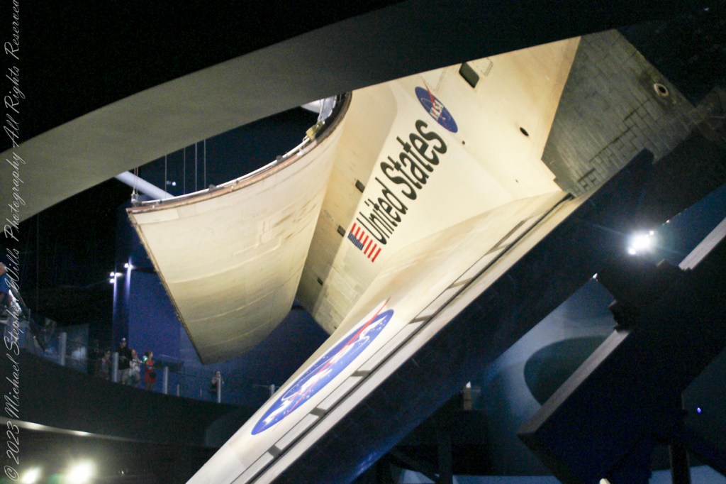
As your gaze shifts towards the rear of Atlantis, the vertical tail fin, or the rear stabilizer, commands attention. Standing about 17 feet tall, this stabilizer is more than just a rudder; it’s a critical component for maintaining the shuttle’s stability during the different phases of its mission. During the launch, it helps keep the shuttle on course as it ascends through the atmosphere. In space, it plays a minimal role, but upon re-entry, it becomes vital again, ensuring the shuttle remains stable and oriented correctly as it descends through the atmosphere, allowing for a safe landing.

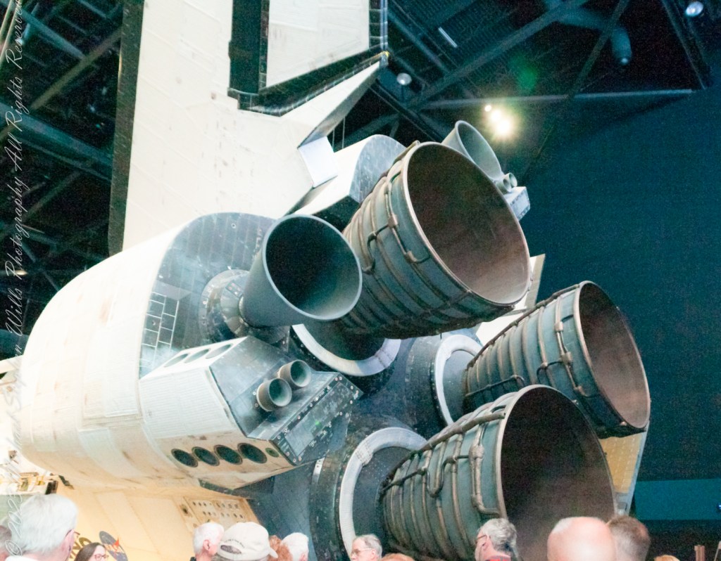
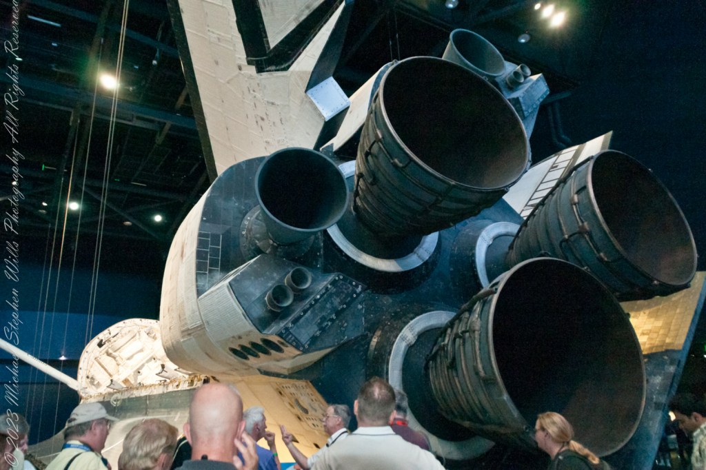
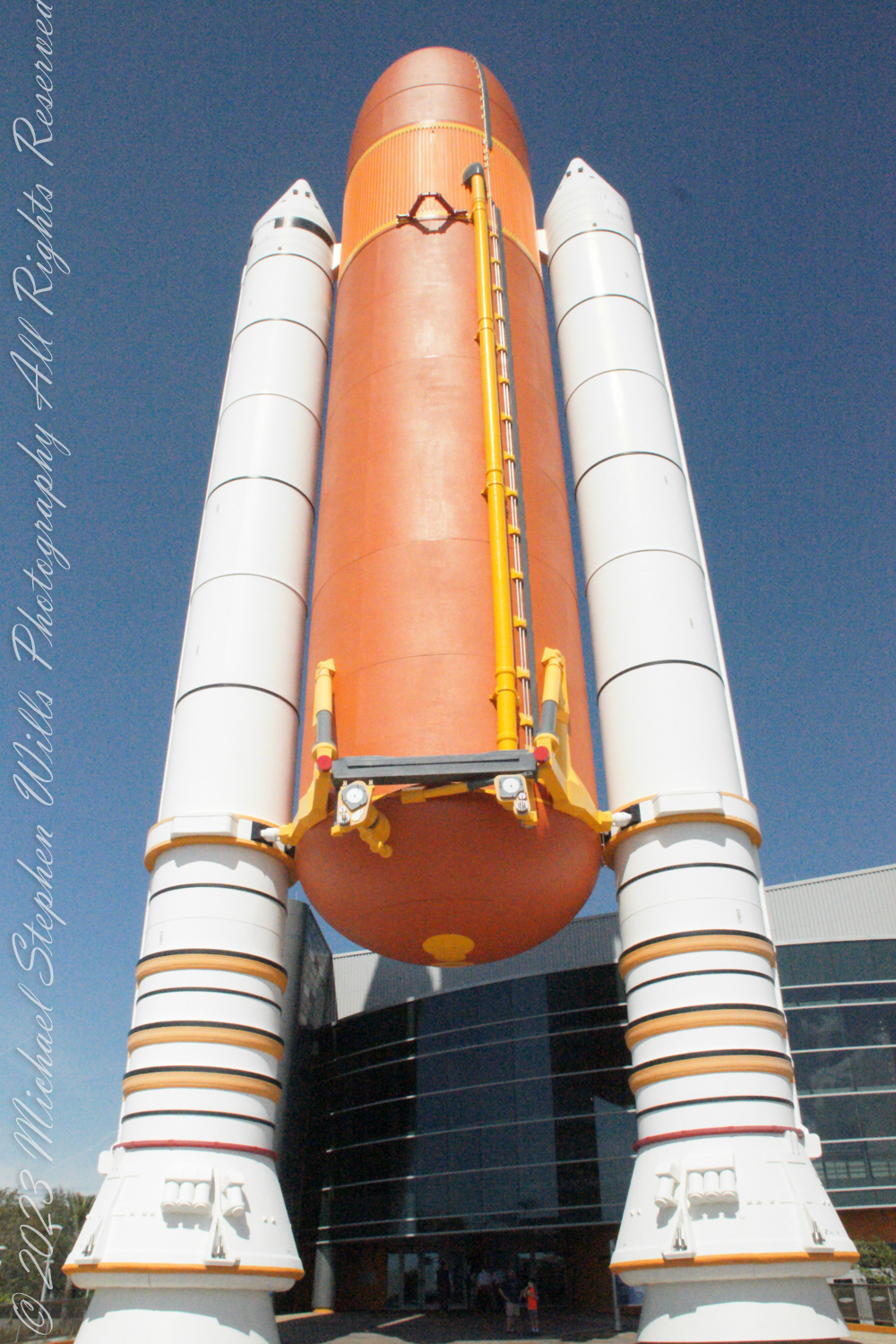
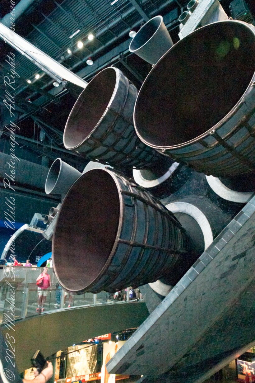
In this exploration of Atlantis, after the wings and stabilizer, we encounter the heart of the shuttle’s propulsion system: its onboard engines. The Space Shuttle Main Engines (SSMEs), three in total, are marvels of engineering, capable of producing a combined thrust of over 1.2 million pounds. These liquid-fueled engines play a crucial role in propelling the shuttle from the launch pad into orbit. What’s fascinating is their ability to throttle up or down depending on the phase of the launch, providing the precise amount of power needed at any given moment. The engines are fed by the External Tank, the only part of the shuttle not reused, which carries the liquid hydrogen and liquid oxygen needed for combustion. Upon reaching orbit, the Orbital Maneuvering System (OMS) engines take over, allowing Atlantis to navigate the vacuum of space with finesse, adjusting its orbit and facilitating the meticulous maneuvers required for satellite deployment or docking with the International Space Station.

Walking away from the Atlantis exhibit, what stays with you is not just the sight of this magnificent spacecraft but an appreciation for the ingenuity and dedication that went into its design. Every wing, every tile on the stabilizer, and every roar from the engines tell a story of human curiosity, the drive to explore beyond our confines, and the relentless pursuit of knowledge. The Space Shuttle Atlantis is more than a machine; it’s a symbol of what humanity can achieve when we dare to dream big and work tirelessly towards those dreams. So, as you look up at the night sky, remember the wings that carried our dreams, the stabilizer that kept us on course, and the engines that propelled us into the unknown, reminding us that the final frontier is not so final after all.

Copyright 2024 Michael Stephen Wills All Rights Reserved

Behind the Scenes of the Final Frontier: Our Tour with NASA’s “Launch Director” – 5

Ever wondered about the iconic robotic arms that gracefully danced in space, tethered to the Space Shuttle? Meet Canadarm, a marvel of engineering that transformed space missions. Born from a NASA invitation to Canada in 1969, this robotic arm did more than just move payloads; it became a symbol of international collaboration in space exploration. After the Columbia disaster, its role expanded, ensuring the safety of astronauts with critical inspections. Dive into the captivating journey of Canadarm, where technology meets the stars. Click to discover how a Canadian innovation became a pivotal part of space history.

The Canadarm

The Canadarm is here extended in the foreground and docked in background

The Canadarm, or Canadarm1, officially known as the Shuttle Remote Manipulator System (SRMS) and sometimes referred to as the SSRMS, represents a series of robotic arms utilized aboard the Space Shuttle orbiters. These arms were instrumental in deploying, manipulating, and retrieving payloads. Following the tragic Space Shuttle Columbia disaster, the use of Canadarm became invariably linked with the Orbiter Boom Sensor System (OBSS). The OBSS played a crucial role in examining the shuttle’s exterior for any damages to its thermal protection system, enhancing the safety of subsequent missions.

The genesis of Canada’s involvement in the Space Shuttle program dates back to 1969 when the National Aeronautics and Space Administration (NASA) extended an invitation to Canada. At the outset, the specifics of Canada’s role were unclear, though the need for a manipulator system was immediately recognized as vital. The Canadian firm DSMA ATCON had previously made strides in robotics with the development of a robot designed to load fuel into CANDU nuclear reactors, capturing NASA’s interest. By 1975, a formal agreement was reached between NASA and the Canadian National Research Council (NRC), under which Canada would undertake the development and construction of the Canadarm.

The NRC subsequently awarded the contract for the manipulator to Spar Aerospace (currently known as MDA), under which three distinct systems were to be developed: an engineering model to aid in design and testing, a qualification model for environmental testing to ensure the design’s suitability for space, and a flight unit destined for use in missions. This collaborative effort marked a significant milestone in the use of robotics in space exploration, showcasing international cooperation in advancing space technology.

Copyright 2024 Michael Stephen Wills All Rights Reserved

Behind the Scenes of the Final Frontier: Our Tour with NASA’s “Launch Director” – 1

Discover an insider’s voyage to the heart of NASA’s launch operations with us as we relive the awe-inspiring Kennedy Space Center Tour, where every corner whispers tales of cosmic ventures and human courage.

Introduction

Late winter 2017 my wife Pam and I embarked on an extraordinary adventure that would etch an indelible mark on our memories. On March 2nd, we had the unique privilege of experiencing the Kennedy Space Center through the eyes of a NASA Launch Director. This wasn’t just any tour; it was a journey through the heart of space exploration, a narrative brought to life by someone who had been at the helm of launching dreams into the cosmos.

The Kennedy Space Center, a beacon of human achievement on Florida’s coastline, stood before us, brimming with stories of courage, innovation, and the relentless pursuit of the unknown. As we stepped onto the grounds, we were not just visitors but participants in a legacy stretching back to the earliest days of space travel. The “NASA Launch Director Tour” promised an inside look at the complexities and triumphs of space missions, a perspective few ever witness.

This series of blog posts is an attempt to capture the essence of that day, to share the insights, emotions, and awe-inspiring moments we experienced. From the thunderous silence of the launch pads to the intimate stories of missions past, each post will explore a different facet of our journey. Join us as we relive an unforgettable exploration of human ingenuity and the boundless reaches of space, all through the lens of a day that brought the stars within reach.

Gathering and Introductions

On the negative side, we enjoyed the expertise of “Jeff” who stood in for the retired Launch Director who was “out sick.” On the positive side, our very expensive fee for the tour was refunded. Jeff was everything we could expect from the tour — he had extensive and detailed insider knowledge of NASA and the launch facilities.

Jeff, our substitute guide

We gathered in a media room, an antechamber to the Space Shuttle Atlantis.

Entry to the Atlantis and the

Space Shuttle Atlantis lifted off on its maiden voyage STS-51-J on October 3, 1985. This was the second shuttle mission that was a dedicated Department of Defense mission. It flew one other mission, STS-61-B (the second shuttle night launch) before the Challenger disaster temporarily grounded the shuttle fleet in 1986. Among the five Space Shuttles flown into space, Atlantis conducted a subsequent mission in the shortest time after the previous mission (turnaround time) when it launched in November 1985 on STS-61-B, only 50 days after its previous mission, STS-51-J in October 1985. Atlantis was then used for ten flights from 1988 to 1992. Two of these, both flown in 1989, deployed the planetary probes Magellan to Venus (on STS-30) and Galileo to Jupiter (on STS-34). With STS-30 Atlantis became the first Space Shuttle to launch an interplanetary probe.

The orbiter’s aluminum structure could not withstand temperatures over 175 °C (347 °F) without structural failure. Aerodynamic heating during reentry would push the temperature well above this level in areas, so an effective insulator was needed.

The Thermal protection system (TPS) covered essentially the entire orbiter surface, and consisted of seven different materials in varying locations based on amount of required heat protection:

–Reinforced carbon–carbon (RCC), used in the nose cap, the chin area between the nose cap and nose landing gear doors, the arrowhead aft of the nose landing gear door, and the wing leading edges. Used where reentry temperature exceeded 1,260 °C (2,300 °F).

Reinforced carbon–carbon (RCC) of the nose cap and “chin area”


–High-temperature reusable surface insulation (HRSI) tiles, used on the orbiter underside. Made of coated LI-900 silica ceramics. Used where reentry temperature was below 1,260 °C.
–Fibrous refractory composite insulation (FRCI) tiles, used to provide improved strength, durability, resistance to coating cracking and weight reduction. Some HRSI tiles were replaced by this type.
–Flexible Insulation Blankets (FIB), a quilted, flexible blanket-like surface insulation. Used where reentry temperature was below 649 °C (1,200 °F).

–Low-temperature Reusable Surface Insulation (LRSI) tiles, formerly used on the upper fuselage, but were mostly replaced by FIB. Used in temperature ranges roughly similar to FIB.
–Toughened unipiece fibrous insulation (TUFI) tiles, a stronger, tougher tile which came into use in 1996. Used in high and low temperature areas.
–Felt reusable surface insulation (FRSI). White Nomex felt blankets on the upper payload bay doors, portions of the mid fuselage and aft fuselage sides, portions of the upper wing surface and a portion of the OMS/RCS pods. Used where temperatures stayed below 371 °C (700 °F).
Each type of TPS had specific heat protection, impact resistance, and weight characteristics, which determined the locations where it was used and the amount used.

The shuttle TPS had three key characteristics that distinguished it from the TPS used on previous spacecraft:

Reusable
Previous spacecraft generally used ablative heat shields which burned off during reentry and so could not be reused. This insulation was robust and reliable, and the single-use nature was appropriate for a single-use vehicle. By contrast, the reusable shuttle required a reusable thermal protection system.
Lightweight
Previous ablative heat shields were very heavy. For example, the ablative heat shield on the Apollo Command Module comprised about 15% of the vehicle weight. The winged shuttle had much more surface area than previous spacecraft, so a lightweight TPS was crucial.
Fragile
The only known technology in the early 1970s with the required thermal and weight characteristics was also so fragile, due to the very low density, that one could easily crush a TPS tile by hand.

Reinforced carbon–carbon (RCC) of the nose cap, close-up

The Space Shuttle thermal protection system (TPS) is the barrier that protected the Space Shuttle Orbiter during the searing 1,650 °C (3,000 °F) heat of atmospheric reentry. A secondary goal was to protect from the heat and cold of space while in orbit.


During the launch of STS-27 in 1988, a piece of insulation shed from the right solid rocket booster struck the underside of the vehicle, severely damaging over 700 tiles and removing one tile altogether. The crew were instructed to use the remote manipulator system to survey the condition of the underside of the right wing, ultimately finding substantial tile damage. Due to the classified nature of the mission, the only images transferred to the mission control center were encrypted and of extremely poor quality. Mission control personnel deemed the damage to be “lights and shadows” and instructed the crew to proceed with the mission as usual, infuriating many of the crew. Upon landing, Atlantis became the single-most-damaged shuttle to successfully land. The survival of the crew is attributed to a steel L band antenna plate which was positioned directly under the missing tile. A similar situation would eventually lead to the loss of the shuttle Columbia in 2003, albeit on the more critical reinforced carbon-carbon.

References: extensive sections of the following Wikipedia articles were quoted, "Space Shuttle thermal protection system," "Space Shuttle  Atlantis."

Copyright 2024 Michael Stephen Wills All Rights Reserved

Apollo 1 Anniversary

This post shares photographs and stories from the early history of spaceflight at Cape Canaveral including the tragic Apollo 1 mission and astronaut John Glenn’s first orbital flight.

Continue reading “Apollo 1 Anniversary”

Launch Complex 14 Today

The post provides historical insight into the early space flights at Cape Canaveral, emphasizing their significance and risks.

Continue reading “Launch Complex 14 Today”

Falcon Heavy First Launch

February 6, 2018

Falcon Heavy is a partially reusable super heavy-lift launch vehicle[a] that can carry cargo into Earth orbit, and beyond. It is designed, manufactured and launched by American aerospace company SpaceX.

The rocket consists of a center core on which two Falcon 9 boosters are attached, and a second stage on top of the center core. Falcon Heavy has the second highest payload capacity of any currently operational launch vehicle behind NASA’s Space Launch System, and the fourth-highest capacity of any rocket to reach orbit, trailing behind the SLS, Energia and the Saturn V.

SpaceX conducted Falcon Heavy’s maiden launch on 6 February 2018, at 20:45 UTC. As a dummy payload, the rocket carried a Tesla Roadster belonging to SpaceX founder Elon Musk, with a mannequin dubbed “Starman” in the driver’s seat. The second Falcon Heavy launch occurred on 11 April 2019, and all three booster rockets successfully returned to Earth. The third Falcon Heavy launch successfully occurred on 25 June 2019. Since then, Falcon Heavy has been certified for the National Security Space Launch (NSSL) program.

Falcon Heavy was designed to be able to carry humans into space beyond low Earth orbit, although as of February 2018, SpaceX does not intend to transport people on Falcon Heavy, nor pursue the human-rating certification process to transport NASA astronauts. Both Falcon Heavy and Falcon 9 are expected to eventually be superseded by the Starship launch system, currently being developed.

On 6 February 2018, after a delay of over two hours due to high winds, Falcon Heavy lifted off at 20:45 UTC. Its side boosters landed safely on Landing Zones 1 and 2 a few minutes later. However, only one of the three engines on the center booster that were intended to restart ignited during descent, causing the booster to be destroyed upon impacting the ocean at a speed of over 480 km/h (300 mph).

Initially, Elon Musk tweeted that the Roadster had overshot its planned heliocentric orbit, and would reach the asteroid belt. Later, observations by telescopes showed that the Roadster would only slightly exceed the orbit of Mars at aphelion.

Reference: Wikipedia, “Falcon Heavy

Copyright 2023 Michael Stephen Wills All Rights

Mercury 7 Pre-Launch Facilities

Hosting Astronaut ZZZZZZZ’s and much more

Here is the sixth in a series of photographs centered on the early history of space flight on Cape Canaveral mostly taken during a tour organized by the Cape Canaveral Lighthouse Foundation. “Google” the foundation for details of future tours. Here we explore pre-launch support for the Mercury program, including the first USA Orbital Launch of John Glenn from Launch Complexe 14 (LC 14).

Overview

Leaving LC 1 – 4 (see Post WWII Launch Complexes”), our bus turned onto Central Control Road passing construction on Launch Complex 36 (LC36). In 2015 Blue Origin (Amazon money) leased LC36 where it planned to launch the “New Glenn” vehicle after 2020. I snapped the churned-up sand and construction equipment, not interesting at all IMHO.

Click Any Image for a larger viewe
Corner of Central Control and ICBM Roads. Cape Canaveral Air Force Station.

The “New Glenn” was named in homage to John Glenn, the first American to orbit the earth in 1962. We turned right onto to ICBM Road, headed generally north, following a string of launch complexes along the Altantic shore toward Launch Complex 14 (LC14). A dissapointment was not stopping to walk the Mercury 7 Memorial at the corner of ICBM Road and LC14. Our bus stopped briefly enough for the following snap. It is a memorial because John Glenn, the surviving member of Mercury 7, passed away December 8, 2016 at the age of 95.

Mercury 7 Memorial, just off ICBM Road

I will cover at length the Mercury-Atlas vehicle that powered John Glenn into orbit February 20, 1962. The tie-in between ICBM road and this series of launch complexes is the early space missions were on re-purposed Intercontinental Ballistic Missles (thus, ICBM). “Atlas” is the name of the ICBM used for Colonel Glenn’s 1962 flight. Click on the following image to find labled pushpins for the corner of Central Control and ICBM Roads (upper right), the road to LC14 and Mercury 7 Memorial.

You will also find a pushpin for the Skid Strip, bottom just to right of center. The earliest cruise missle tests (see “Cruise Missles” and Post WWII Launch Complexes” ) included navigation to a landing on non-wheeled “skids.” The strip was maintained in support of the manned and later missions when cargo planes delivered the early space capsules, landing, not skidding hopefully, for transfer to a Pre-Launch facility, Hangar S.

Cape Canaveral Launch Complex 14 and Pre-Launch Support: Hangar S and the Skid Strip

Hangar S is seen below as we passed later in the tour. Built 1957 by the military the 61,300 square feet were acquired by NASA in 1959. The early space capsules were tested here in an vacume chamber to ensure the vehicle supported an breathable atmosphere for the occupants.

The first American space voyager was Ham, a chimpanzee. Ham lived in a residential area on the second floor of Hangar S. For a period of time the Mercury 7 shared the spartan second floor quarters. “The Right Stuff” (a 1984 film from a Tom Wolfe book) included scenes from this episode of the program.

Constructed in 1957, Hangar S served for pre-flight processing from Mercury through the final flight of the Space Shuttle. This is where the Mercury 7 astronauts were first quartered on the second floor and later, is where they stayed prior to flight. The Lunar Orbiter was prepared here.

Comfortable Quarters

In short order arrangements were made for more comfortable quarters, just off the ocean in Cocoa Beach. It was a new hotel given over entirely to the Mercury 7. Pam and I stayed there in 2018 while taking this tour, it is the La Quinta across from the International Palms. We recommend it a clean, comfortable, reasonably price and a great story to share afterwards. The Atlantic Ocean is a five minute walk.

La Quinta Inn was the home of the Mercury 7 Astronauts, 1275 N Atlantic Avenue Cocoa Beach, Florida 32931

I learned from the tour how the hotel was donated to the Mercury 7 by a private individual. They owned the hotel. Here is a very informative sign just off the La Quinta lobby with their names. Each first mission, as named by the astronaut, is listed.

La Quinta Inn was the home of the Mercury 7 Astronauts, 1275 N Atlantic Avenue Cocoa Beach, Florida 32931
View of the hotel built for and first owned by the Marcury 7 astronauts. They lived here in the early days of the USA space program.

Blastoff!!

Next post will feature images of LC14 from 2018.

Launch of Friendship 7, the first American manned orbital space flight. Astronaut John Glenn aboard, the Mercury-Atlas rocket is launched from Pad 14. Public Domain Photograph by NASA.

ClickMe for the next post in this series, “Launch Complex 14 Today.”

ClickMe for the first post in this series, “Cape Canaveral Lighthouse.”

Sources of information for this post: I used information from the Wikipedia site for the key words John Glenn, Launch Complex 14, Mercury-Atlas, Launch Complex 36. Plus a “google” on “Hangar S History” that found an excellent page hosted on the NASA site. Cover photo of Friendship 7 Launch my be found on Flickr in “NASA on the Commons” photostream.

Copyright 2022 Michael Stephen Wills All Rights Reserved.

Into the Atacama Desert

where the Mars Rover was tested

NASA uses the rugged terrain of the Atacama as an analog for Mars. There the Mars Rover was tested.

Click any photograph for a larger view and use Ctrl-x to zoom in closer.

These photographs, taken from our tour bus….

….enroute to Humberstone World Heritage Site….

Northeast corner of Manuel Bulnes and Oscar Bonilla

Speak for themselves.

Marble memorial to traffic accident victim.

Click me for the next post of this series.

Click me for the first post of this series.

References

Website: mars.nasa.gov/resources/8351/atacama-landscape/

Copyright 2020 Michael Stephen Wills All Rights Reserved

International Space Station

pre-dawn sky event

December 23rd, sky clear at 6:30 am, the International Space Station (ISS) passed through the zenith with a waning crescent, a bowl filled with earthglow, in the southeast. On December 22nd I received the following email from NASA advising me of the event.

HQ-spotthestation@mail.nasa.gov

Sun 12/22/2019 7:00 PM

Time: Mon Dec 23 6:30 AM, Visible: 6 min, Max Height: 87°, Appears: 10° above SW, Disappears: 11° above ENE

Visit the NASA site to research if ISS viewing is possible from your location.

Here is another photograph of the crescent moon filled with earthglow.

Click photograph for the expanded view. To do this from WordPress Reader, you need to first click the title of this post to open a new page.
Copyright 2020 All Rights Reserved Michael Stephen Wills

Earthglow

pre-dawn sky event

December 23rd, sky clear at 6:30 am, the International Space Station passed through the zenith with a waning crescent, a bowl filled with earthglow, in the southeast. Here is a photograph of a waning moon above Cornell University from October 2017.

Copyright 2024 All Rights Reserved Michael Stephen Wills