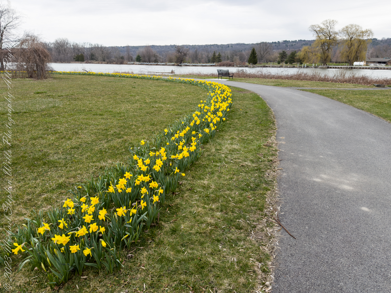
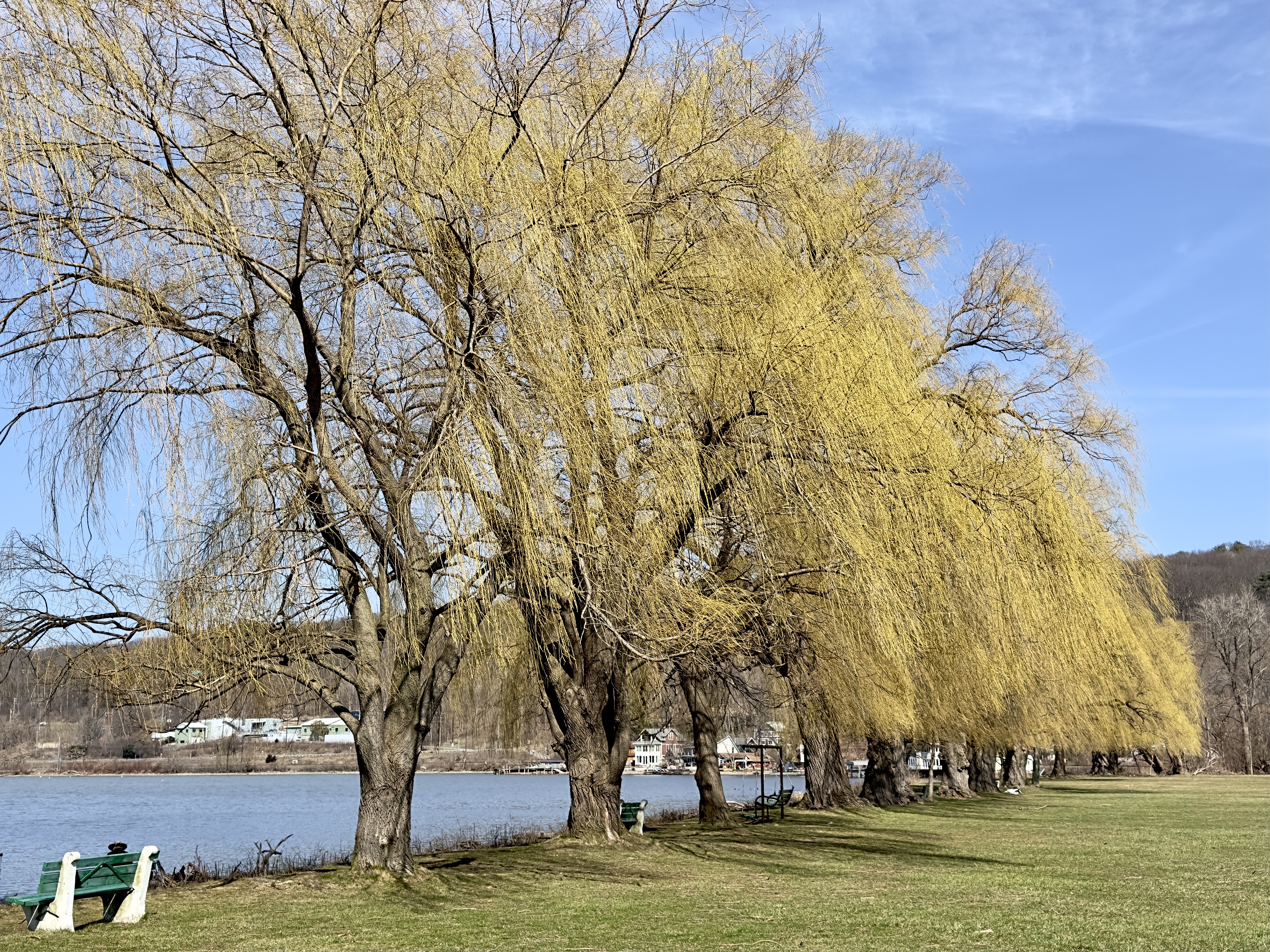
As the crisp air of spring begins to soften and the last remnants of winter recede, you might find yourself drawn to the outdoors, eager to participate in the age-old tradition of spring cleaning. It is a time of renewal, of clearing away the old to make way for the new. In Ithaca, this period of rejuvenation extends beyond the confines of cluttered homes and into the expansive natural landscape, as shown in the photograph before you.
Tidying the Shores
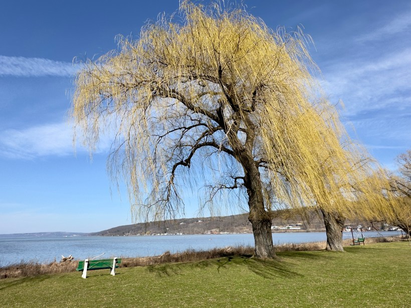
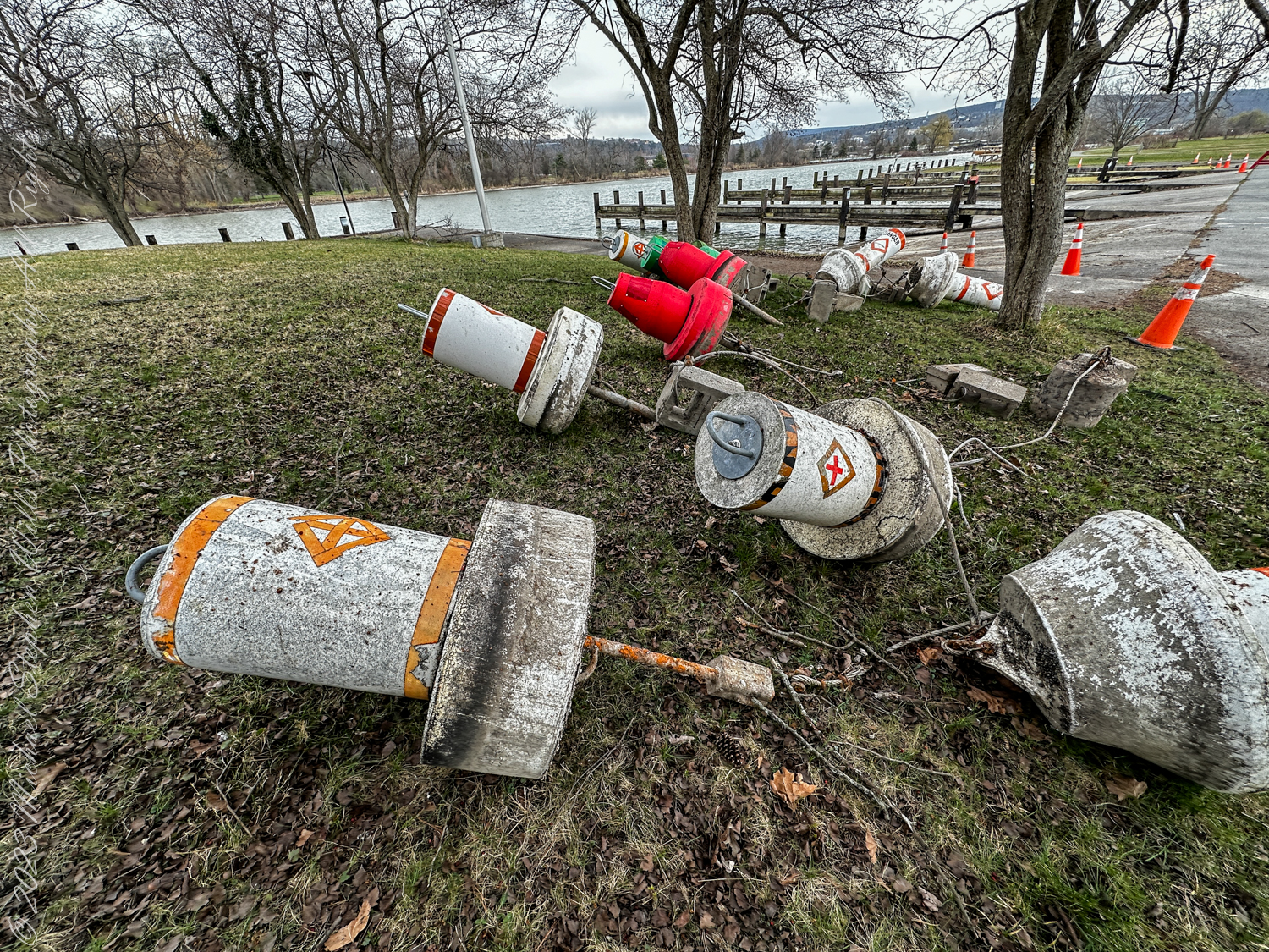
There, on the shores of Cayuga Lake, the scene is a stark contrast to the neat rows of daffodils you admired yesterday. Instead, navigation buoys, those steadfast guides of the waterways, lie upended and scattered – casualties of the winter’s harshness or perhaps the diligent work of park employees preparing for the upcoming boating season. These buoys, usually afloat, marking safe passage for vessels, are now being tended to, maintained, and readied. It is an essential process, akin to the annual spring clean, ensuring the safety and smooth sailing in the months to come.
Guardians of the Waterways
Let’s delve into the history these buoys are part of. You, as a curious observer, are witnessing a fragment of a narrative that stretches back over a century. These navigational buoys are descendants of the earliest markers that adorned the inland waters of New York State and the Erie Canal, of which Cayuga Lake is an integral part.
The Erie Canal and Cayuga’s Connection
The Erie Canal, an engineering marvel of the 19th century, opened in 1825, transforming New York and the entire Great Lakes region. It was the superhighway of its time, connecting the Atlantic Ocean to the Great Lakes, and thereby shaping the course of economic and social history in the United States. Cayuga Lake, connected to this system via the Cayuga-Seneca Canal, was part of this vast network of navigable waters.
Navigation Buoys: Beacons of Progress
As commerce flourished, so too did the need for reliable navigation. The buoys, then as now, served as critical signposts, ensuring that vessels could traverse these waterways safely. Imagine the countless boats that relied on these markers – from the large freighters carrying goods to the smaller craft bearing passengers – each buoy a sentinel ensuring their safe passage.
Modern Sentinels
Today, the navigation buoys on Cayuga Lake and other inland waters continue this legacy. They are the modern sentinels of the deep, equipped with the latest technology to guide the way. Just as the Erie Canal once heralded a new era of travel and trade, these buoys now symbolize the enduring importance of safe and efficient water transportation.
The Future of Inland Navigation
As you reflect upon the photograph, consider the ongoing narrative of these buoys and the waterways they mark. In a world increasingly concerned with sustainable modes of transportation, the historical importance of these channels resurfaces. The waterways that once fueled the expansion of a nation may once again play a pivotal role, this time in the quest for greener alternatives to overland routes.
Conclusion: A Cycle of Renewal
The upturned buoys in Cass Park, ready for their spring cleaning, are a microcosm of the cyclical nature of life and progress. They remind you that renewal is not just about beauty; it is also about preserving the functionality and safety that allow society to move forward. Just as the spring cleaning in your home ushers in a new season of clarity and freshness, the maintenance of these navigational aids renews the commitment to a legacy of safe passage – a promise made by the generations that have sailed these waters since the days of the Erie Canal.